
How to Choose the Right Flanged Type Globe Valve
Choosing the right Flanged Type Globe Valve requires more than comparing prices or connection sizes. The valve must match the pipeline’s pressure, temperature, flow direction, and operating frequency. A steam service may demand heat-resistant materials and suitable packing. A corrosive fluid may require carefully selected body and trim materials. Small details matter.
In practical installations, flange alignment can affect gasket performance and maintenance time. A heavy handwheel may also signal excessive differential pressure or poor sizing. Check the manufacturer’s flow coefficient, pressure-temperature ratings, face-to-face dimensions, and allowable leakage class. Confirm that the flange standard matches the connected pipework. Never rely on appearance alone. A polished body does not prove dependable performance.
Reliable selection combines field experience, engineering calculations, and verified documentation. Review certified test records, material certificates, and operating limits from an established manufacturer. Ask whether spare parts remain available after installation. Consider access around the valve, especially in crowded pump rooms or narrow process skids. Maintenance crews need enough clearance to remove the bonnet and replace packing safely.
No selection is perfect. Actual service conditions can change. Fluid contamination, cycling, vibration, and unexpected pressure surges may expose weaknesses that a catalog cannot show. That is why the final decision should be checked by a qualified engineer and compared with applicable standards. The best Flanged Type Globe Valve is not simply the largest or cheapest option. It is the valve that provides controlled flow, dependable sealing, safe maintenance, and predictable service under real operating conditions.
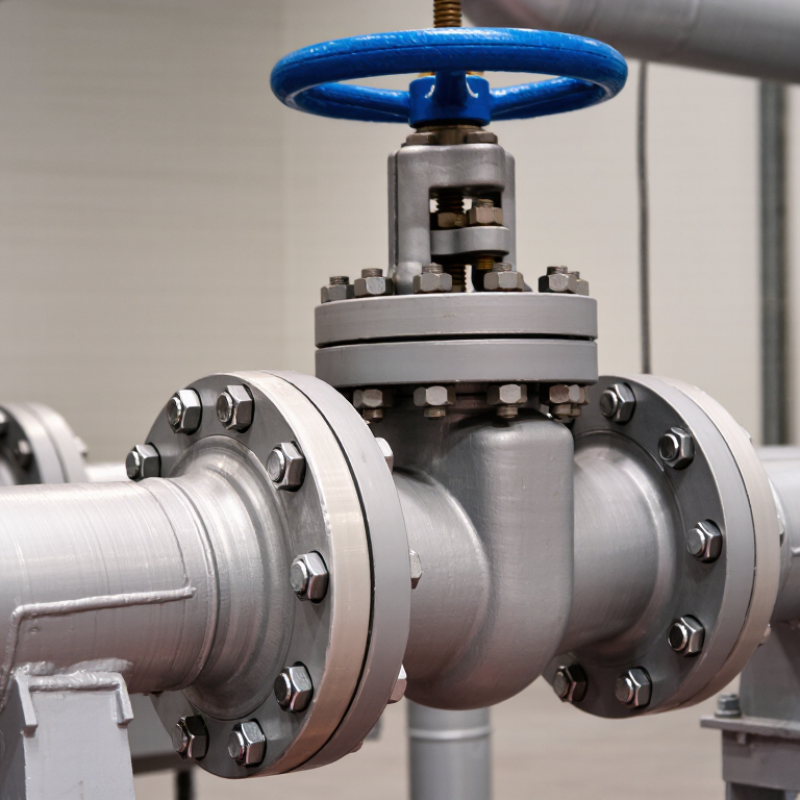
Define the Operating Conditions for a Flanged Globe Valve
How to Choose the Right Flanged Type Globe Valve
Define the Operating Conditions for a Flanged Globe Valve
Choosing a flanged globe valve starts with the real operating conditions, not the pipe size alone. Record the fluid, pressure, temperature, flow rate, and expected operating frequency. Steam at 180°C requires different materials and packing than clean water at ambient temperature. Dirty fluids may also damage the seating surfaces faster.
Check both normal and abnormal conditions. A valve rated for 10 bar may face higher pressure during startup or thermal expansion. Specify the maximum pressure, minimum temperature, and pressure drop across the valve. Excessive pressure loss can increase pumping costs and create noise. Measure the required flow carefully, because an oversized valve often operates near its seat and controls poorly.
The fluid’s chemistry deserves close attention. Corrosive liquids can attack the body, stem, or gasket, even when the visible pipework looks suitable. Consider viscosity, suspended solids, flashing, and possible cavitation. These details influence the body material, trim, bonnet design, and actuator selection. Flange dimensions and pressure classes must match the connected piping and applicable standards.
Field experience shows that incomplete data causes many selection errors. A neat calculation can still be wrong. Recheck readings from old gauges, and confirm whether the valve will remain accessible for inspection. Manual operation may be practical for occasional adjustment, but frequent cycling usually needs a properly sized actuator. Leave room for maintenance, because a valve that cannot be serviced is not a reliable installation.
How to Choose the Right Flanged Type Globe Valve - Define the Operating Conditions for a Flanged Globe Valve
| Operating Parameter | Information to Confirm | Why It Matters for Valve Selection | Typical Engineering Data |
|---|---|---|---|
| Fluid or Service | Water, steam, air, gas, oil, chemicals, slurry, or corrosive media | Determines the body, bonnet, stem, seat, packing, and trim materials | Clean water, saturated steam, thermal oil, compressed air, and non-corrosive process liquid |
| Normal Pressure | Steady-state upstream and downstream pressure | Provides the basis for estimating load, pressure drop, and required pressure class | Record the normal operating pressure in bar(g), kPa(g), or psi(g) |
| Maximum Allowable Pressure | Maximum upstream pressure, including upset and start-up conditions | The valve pressure rating must not be lower than the maximum allowable operating pressure at the design temperature | Include pump shut-off pressure, blocked-outlet pressure, and pressure surges |
| Operating Temperature | Normal, minimum, maximum, start-up, and shutdown temperatures | Temperature changes the pressure rating and affects gasket, packing, seat, and body material performance | Specify temperature in °C or °F and identify whether it is fluid or ambient temperature |
| Flow Rate | Minimum, normal, maximum, and any turndown requirement | Used to size the valve and calculate the required flow coefficient, commonly expressed as Cv or Kv | Provide mass flow or volumetric flow with the fluid density and viscosity |
| Pressure Drop | Available pressure difference across the valve | A globe valve can provide good throttling control, but excessive pressure drop may cause noise, vibration, erosion, or cavitation | Define allowable pressure loss at minimum, normal, and maximum flow |
| Flow Direction | Required inlet and outlet orientation | Correct flow direction supports stable throttling and reduces the risk of abnormal plug movement | For many globe-valve designs, flow is arranged under the plug for general throttling service; follow the valve flow arrow |
| Control or Isolation Duty | Frequent modulation, occasional throttling, or full-open/full-closed isolation | Frequent throttling requires suitable trim geometry, actuator capability, and resistance to erosion | State the expected operating cycles per hour, day, or year |
| Fluid Cleanliness | Presence of solids, rust, fibers, crystals, or suspended particles | Particles can damage seating surfaces and accelerate trim erosion | Clean service is generally preferred; severe slurry service may require a different valve design |
| Noise, Cavitation, and Flashing | Vapor-pressure margin and pressure reduction through the valve | High pressure drop in liquid service can cause cavitation; gas and steam service can generate excessive aerodynamic noise | Provide fluid vapor pressure, critical pressure data where applicable, and allowable noise level |
| Selection Item | Common Options | Recommended Selection Logic | Important Check |
|---|---|---|---|
| Valve Size | Nominal pipe size, typically DN15 to DN600 or larger depending on design | Select the valve using the required flow coefficient and acceptable velocity rather than simply matching the pipe size | Verify minimum controllable flow, maximum velocity, and line-size compatibility |
| Pressure Class | ASME Class 150, 300, 600, 900, or higher; other systems may use PN ratings | Choose a class based on design pressure and design temperature together | Pressure ratings are material- and temperature-dependent; do not compare Class and PN values as direct equivalents |
| Flange Standard | ASME B16.5, ASME B16.47, EN 1092-1, or another specified piping standard | The valve flange must match the piping flange standard, nominal size, pressure designation, facing, and bolt pattern | Confirm raised face, flat face, ring-type joint, gasket type, and facing finish |
| Body Material | Carbon steel, stainless steel, alloy steel, bronze, or other compatible alloys | Select according to corrosion resistance, temperature, pressure, and mechanical strength requirements | Check material compatibility with the fluid, chloride content, oxygen content, and any sour-service requirements |
| Bonnet Configuration | Bolted bonnet, pressure-sealed bonnet, extended bonnet, or cryogenic bonnet | Use a construction suitable for pressure, temperature, maintenance access, and insulation requirements | Extended bonnets are commonly considered for low-temperature or cryogenic service to protect stem seals |
| Trim and Seat | Metal seat, soft seat, hardened trim, reduced-port trim, or multi-stage trim | Use metal seating for high temperature and demanding erosion service; use soft seating only within its temperature and compatibility limits | Confirm leakage class, shutoff requirement, differential pressure, and expected throttling duty |
| Stem Arrangement | Rising stem with outside screw and yoke, or another specified configuration | A rising stem provides visible travel indication and is widely used for flanged globe-valve designs | Allow sufficient clearance above the valve for stem travel, handwheel removal, and maintenance |
| Actuation | Handwheel, pneumatic actuator, electric actuator, or hydraulic actuator | Manual operation suits infrequent adjustment; powered actuation suits remote, automatic, or high-cycle service | Calculate required thrust or torque using maximum differential pressure and seating load |
| Packing and Gasket | Flexible graphite, PTFE-based packing, braided packing, spiral-wound gasket, or ring-type gasket | Choose sealing materials for the fluid, temperature, emissions requirements, and flange facing | Verify chemical compatibility, fire-safe requirements, fugitive-emission requirements, and applicable regulations |
| Special Service Requirements | Oxygen, hydrogen, toxic fluid, sour service, vacuum, fire-safe, low-emission, or cryogenic service | Specify additional cleaning, material controls, testing, or design features before issuing the purchase specification | Reference the applicable project, piping, safety, and inspection standards |
| Service Condition | Suitable General Configuration | Key Design Considerations | Conditions Requiring Additional Review |
|---|---|---|---|
| Clean Water or Cooling Water | Flanged body with corrosion-compatible trim and standard packing | Check corrosion allowance, water chemistry, pressure class, and allowable pressure loss | Seawater, high-chloride water, abrasive solids, and severe throttling |
| Saturated Steam | Metal-seated globe valve with temperature-rated body, trim, packing, and gasket | Use the steam pressure-temperature condition for rating selection; consider drainage and erosion | Superheated steam, high velocity, high cycle count, and severe pressure reduction |
| Thermal Oil or Hot Process Liquid | Metal-seated valve with temperature-compatible packing and gasket materials | Consider thermal expansion, fire safety, fluid viscosity, and maximum operating temperature | Very high temperature, flammable service, coking fluids, and frequent cycling |
| Compressed Air or Non-Corrosive Gas | Flanged globe valve with suitable gas-tight packing and appropriately sized trim | Check gas velocity, noise, pressure drop, and leakage requirements | Oxygen service, toxic gas, hydrogen, high pressure ratio, or explosive atmosphere |
| Corrosive Chemical Liquid | Corrosion-resistant body and trim, selected from verified material-compatibility data | Evaluate concentration, temperature, contaminants, and corrosion rate | Mixed chemicals, oxidizing media, chlorides, wet chlorine, and unknown composition |
| Liquid with Cavitation Risk | Anti-cavitation trim, staged pressure reduction, or an alternative control-valve design | Calculate pressure recovery, vapor pressure, and cavitation index using actual operating data | Noise, vibration, flashing, unstable flow, or severe trim damage |
| Low-Temperature or Cryogenic Service | Low-temperature body material with an extended bonnet and compatible seat and packing system | Review impact toughness, contraction, insulation clearance, and atmospheric moisture control | Temperatures below the qualified material range, oxygen service, and rapid thermal cycling |
| Data Sheet Field | Required Entry | Example of a Complete Entry |
|---|---|---|
| Valve Function | Isolation, throttling, control, bypass, or drain service | Frequent throttling with tight shutoff during shutdown |
| Nominal Size | Pipe size and valve size | DN100 line; final valve size confirmed by flow coefficient calculation |
| Design Pressure and Temperature | Maximum pressure and temperature used for mechanical design | Design pressure 30 bar(g); design temperature 250 °C |
| Normal Operating Point | Normal inlet pressure, outlet pressure, temperature, and flow | Inlet 18 bar(g), outlet 12 bar(g), 210 °C, and 22 m³/h |
| Minimum and Maximum Flow | Operating range and required turndown | Minimum 5 m³/h, normal 22 m³/h, maximum 35 m³/h |
| Fluid Properties | Density, viscosity, vapor pressure, molecular weight, and solids content where applicable | Fluid properties supplied at minimum, normal, and maximum operating temperatures |
| End Connection | Flange standard, size, pressure class, facing, and gasket arrangement | Flanged ends, ASME pressure class specified by piping design, raised-face connection |
| Materials | Body, bonnet, stem, plug, seat, packing, and gasket materials | Materials selected after pressure-temperature and chemical-compatibility review |
| Testing and Inspection | Shell test, seat test, functional test, material certification, and special inspection requirements | Pressure testing and inspection requirements defined in the project valve specification |
| Installation Constraints | Face-to-face dimension, flow direction, orientation, access, and actuator clearance | Horizontal pipeline, upward stem orientation, accessible handwheel, and required maintenance clearance |