
How to Choose a Power Transformer Fuse in 2026
Choosing a Power Transformer Fuse in 2026 is not a matter of matching one number on a nameplate. The fuse must suit the transformer’s voltage, rated current, inrush behavior, and available fault current. It also needs to coordinate with upstream and downstream protection. A mismatch can cause nuisance operations—or leave equipment exposed longer than intended.
Distribution-protection author Thomas A. Short’s published work emphasizes coordinating protective devices with the system they serve. In practical terms, that means checking the transformer data, the fuse’s time-current curve, and the installation conditions together. Consider a 500 kVA unit: its primary voltage and connection affect load current, while magnetizing inrush can influence fuse selection. The available fault current matters, too. A fuse that looks suitable in a catalog may not perform as expected at a particular site.
Details matter. So do assumptions. Confirm ratings against current manufacturer documentation, and have a qualified engineer review the selection for the actual system. Standards and product offerings can change by region and application. I would not rely on a single rule of thumb here; real installations can be messier than design examples. The sections ahead explain the key ratings, coordination checks, common selection errors, and practical questions to ask before choosing a Power Transformer Fuse. A careful review now can prevent avoidable outages later.
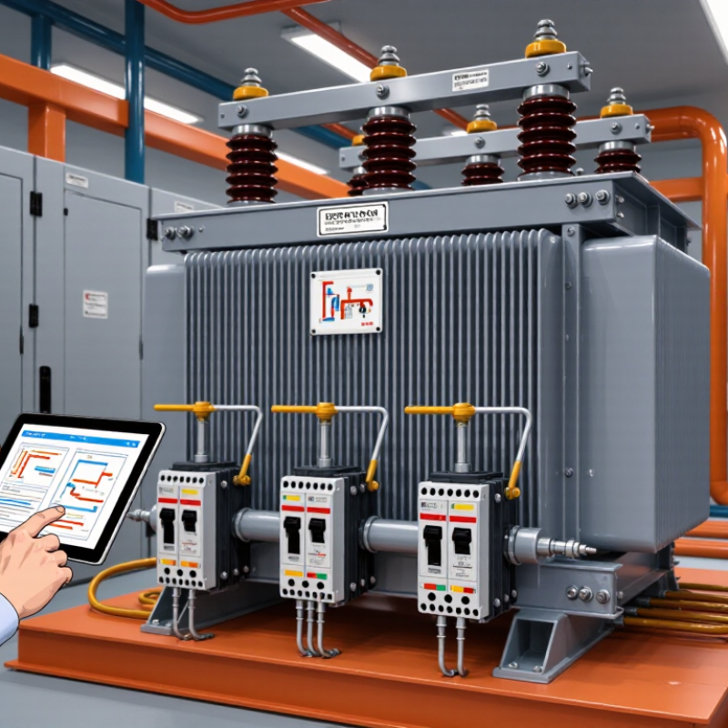
Identify the Transformer’s Ratings and Operating Conditions
Before choosing a power transformer fuse, record the nameplate kVA, primary and secondary voltages, phase, impedance, and connection type. These values define the electrical baseline; they do not, alone, determine fuse size. The U.S. Department of Energy’s 2016 Distribution Transformers Technical Support Document describes a domestic fleet of roughly 60 million distribution transformers, spanning varied capacities and voltage classes. That scale highlights why ratings must be checked for the actual unit, not guessed from appearance.
Next, note operating conditions: expected load profile, ambient temperature, inrush current, and available fault current. A transformer energized after a long shutdown may draw a brief magnetizing surge, so a fuse with an unsuitable time-current curve can operate unnecessarily. IEEE C57.91’s loading guidance emphasizes the effects of load and temperature on transformer aging. Match the fuse curve to transformer withstand limits and downstream protection, then have a qualified engineer verify coordination against the site’s fault-current study. A tidy calculation can still miss a seasonal load peak; field conditions deserve a second look.
Tips: Photograph the nameplate, then compare its ratings with measured load and the one-line diagram. Record uncertainty, too. It matters.
How to Choose a Power Transformer Fuse in 2026 — Identify the Transformer’s Ratings and Operating Conditions
| Data Dimension | What to Identify | Illustrative Data or Calculation | Why It Matters for Fuse Selection |
|---|---|---|---|
| Transformer apparent-power rating | Rated capacity in kVA or MVA, taken from the nameplate. | Example: 100 kVA, three-phase transformer. | Capacity is used with primary voltage to calculate rated primary current. It is not, by itself, a fuse-size recommendation. |
| Primary voltage and system configuration | Primary line-to-line voltage for three-phase equipment, or winding voltage for single-phase equipment; also record the system grounding arrangement. | Examples: 13.2 kV three-phase primary; 7.2 kV single-phase primary. | Voltage and system configuration affect the applicable fuse class, insulation level, installation method, and protection arrangement. |
| Rated primary current | Use the nameplate value when available. Otherwise, calculate from kVA and primary voltage. | Three-phase: I = kVA × 1,000 ÷ (√3 × line-to-line volts). A 100 kVA, 13.2 kV unit has approximately 4.37 A primary current. Single-phase: I = kVA × 1,000 ÷ volts; a 25 kVA, 7.2 kV unit has approximately 3.47 A. | Rated current is a starting point for evaluation. Fuse selection must also account for inrush, overload protection, fault levels, and coordination. |
| Secondary rating and load | Record secondary voltage, phase, full-load current, expected demand, and load growth. | Example: a 100 kVA, three-phase transformer rated 480 V secondary has approximately 120 A secondary full-load current. | Secondary protection and load characteristics affect the required coordination between primary and secondary protective devices. |
| Transformer impedance and available fault current | Record nameplate impedance (%Z) and determine the available fault current at the installation point. | Example nameplate value: 5.75% impedance. The actual fault current depends on the source and system impedance as well as the transformer. | These values help verify interrupting capability and whether the selected protection can coordinate with downstream devices. |
| Energization inrush | Review the manufacturer’s inrush data, energization conditions, and any switching or reclosing practices. | Inrush magnitude and duration vary with transformer design, residual core flux, switching angle, and source impedance. | A fuse must ride through expected magnetizing inrush while still providing the intended protection. Do not choose a fuse solely from full-load current. |
| Fuse type and time-current curve | Identify the intended fuse technology and compare its time-current characteristics with transformer damage limits and downstream protection. | Examples include current-limiting fuses and expulsion-type fuses; ratings and application rules differ by fuse class and equipment. | Fuse types are not interchangeable simply because their nominal ampere ratings match. Check the applicable product data and coordination curves. |
| Operating environment | Record ambient temperature, altitude, enclosure or vault conditions, ventilation, contamination, and exposure to weather. | Example site conditions: outdoor installation, high elevation, or a poorly ventilated enclosure. | Environmental conditions and installation details may affect equipment ratings and the suitability of the fuse and its holder. |
| Protection and coordination requirements | Define the required response to transformer faults, secondary faults, and overloads; identify upstream and downstream devices. | Review system one-line diagrams and time-current curves for the complete protective-device chain. | The fuse should meet the protection objective without unnecessary operation during normal loading or transformer energization. |
| Installation and compliance checks | Confirm fuse voltage rating, continuous-current rating, interrupting rating, mounting compatibility, and applicable local requirements. | Use the equipment nameplate, fuse manufacturer’s application data, and applicable electrical codes and standards. | Final selection depends on the specific system and equipment. Have the design checked by a qualified electrical professional. |
Important: The numerical examples are for illustrating current calculations only; they are not recommended fuse sizes. Select the fuse using the transformer manufacturer’s guidance, system study, fuse time-current data, equipment ratings, and applicable codes and standards.